qNinja

Initialization Using a USB Serial Adapter

What You'll Need

  • Arduino IDE
  • USB Serial Adapter and Cable
  • qNinjaLite Device
  • Binary file (Download and save to your PC)

Preparing Arduino IDE

  1. Download the latest version of the Arduino IDE from the official Arduino website and install it on your computer.
  2. Open the installed Arduino IDE.
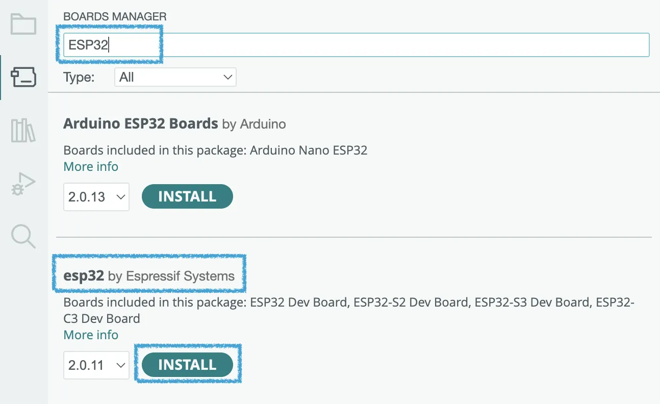
  3. Select "Tools" > "Board" > "Boards Manager..." from the tools menu.
  4. In the Boards Manager's search bar, type "ESP32" and click the "Install" button for "ESP32 by Espressif Systems".
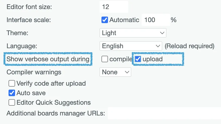
  5. From the Arduino IDE's "File" menu, select "Preferences" and check the "Show verbose output during upload" option to display detailed information during upload and compilation processes.

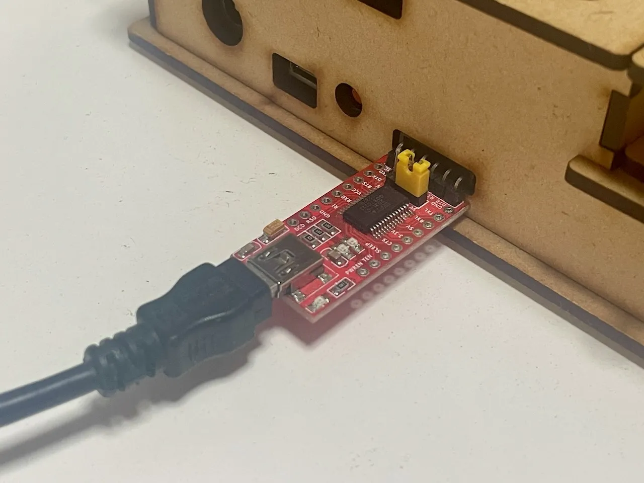
Preparing USB Serial Adapter

  1. Connect the USB Serial Adapter to your PC using the included cable.
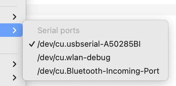
  2. Open the "Tools" > "Port" menu in the Arduino IDE and select the port that corresponds to your USB Serial Adapter.
  3. Select a board by navigating to "Tools" > "Board" > "ESP32" and choosing "ESP32S3 Dev Module" from the list.
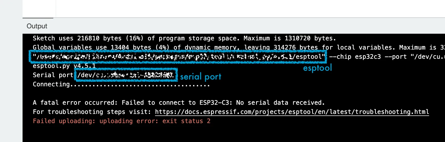
  4. Attempt to upload any sketch. This process is not to successfully upload but to find paths of command "esptool" and the serial port used for writing. Please press the "→" upload button. If "Show verbose output during upload" is enabled, the paths to esptool and serial port will be displayed. Please note thiese paths.

Writing to the qNinjaLite Device

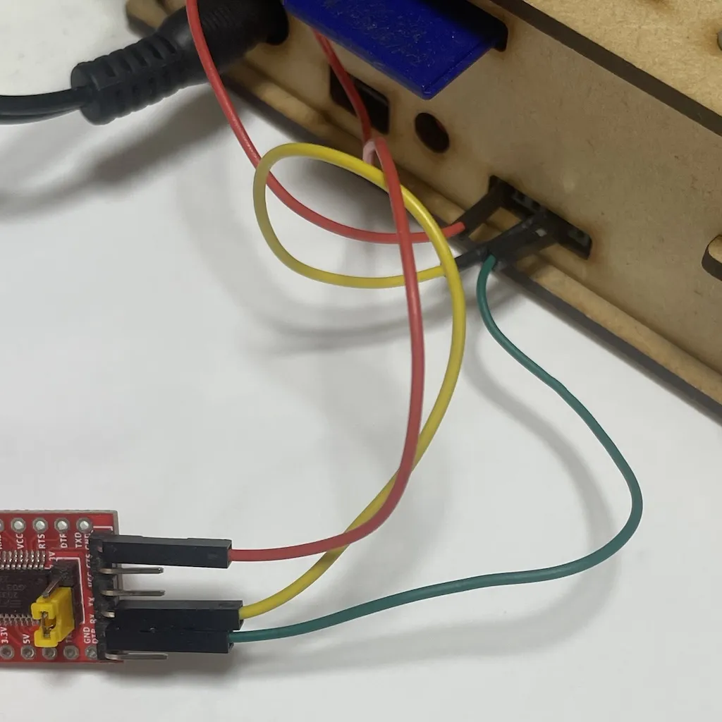
  1. Connect the USB Serial Adapter to the back of the qNinjaLite device.
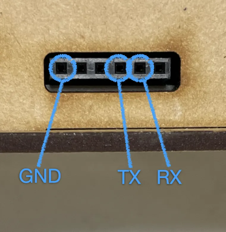
    If the pin configuration of your USB adapter does not match that of the qNinjaLite's serial connector, please connect them using jumper wires. Serial communication is possible as long as the GND, RX, and TX pins are connected.
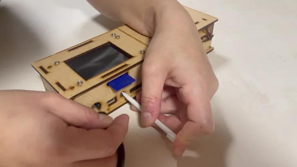
  2. Press and hold the "BOOT" button on the back of the qNinjaLite device while turning on the power to enter programming mode.
    How to start in bootloader mode
  3. Open the Terminal (on macOS or Linux) or Command Prompt (on Windows) and execute the following command to erase the device's flash memory. Please replace "/path/to/esptool", "/path/to/serial", and "/path/to/binary" with the actual paths. /path/to/esptool --port SERIAL_PORT erase_flash
  4. Next, write the new firmware to the device./path/to/esptool --port /path/to/serial write_flash 0x0 /path/to/binary

USBシリアルアダプタを使用した初期化

用意するもの

  • Arduino IDE
  • USBシリアルアダプタとケーブル
  • qNinjaLiteデバイス
  • バイナリファイル (ダウンロードして保存してください)

Arduino IDEの準備

  1. Arduinoの公式ウェブサイトから最新版のArduino IDEをダウンロードし、お使いのコンピュータにインストールします。
  2. インストールしたArduino IDEを開きます。
  3. ツールメニューから「ボード」>「ボードマネージャ...」を選択します。
  4. ボードマネージャの検索バーに「ESP32」と入力し、検索結果から "ESP32 by Espressif Systems" を見つけて「インストール」ボタンをクリックします。
  5. Arduino IDEの「ファイル」メニューから「環境設定」を選択し、「詳細情報を表示する」オプションにチェックを入れます。これにより、アップロードやコンパイル時に詳細な情報が表示されるようになります。

USBシリアルアダプタの準備

  1. 付属のケーブルを使用して、USBシリアルアダプタをPCに接続します。
  2. Arduino IDEの「ツール」>「ポート」メニューを開き、使用しているUSBシリアルアダプタに対応するポートを選択します。
  3. ボードを選択します。「ツール」メニューから「ボード」>「ESP32」を選び、リストから「ESP32S3 Dev Module」を選択します。
  4. 任意のスケッチを選択し、アップロードを実行してみます。このプロセスは、実際にアップロードを成功させることではなく、書き込みに使うコマンド "esptool" とシリアルポートの場所を調べることが目的です。 「→」のアップロードボタンを押してください。 この時、「詳細情報を表示する」が有効になっていれば、esptoolとシリアリポートのパスが表示されます。このパスをメモしておいてください。

qNinjaLiteデバイスへの書き込み

  1. qNinjaLiteデバイスの背面にUSBシリアルアダプタを接続します。シリアルコネクタのピン配置は次の写真のようになっています。
    お使いのUSBアダプタのピン配置がqNinjaLiteのシリアルコネクタのピン配置と一致しない場合は、ジャンプワイヤなどでつないでください。GND、RX、TXの3本だけが繋がっていればシリアル通信ができます。
  2. qNinjaLiteデバイスの裏面にある「BOOT」ボタンを押しながら電源を入れます。これにより、デバイスがプログラミングモードに入ります。
    How to start in bootloader mode
  3. ターミナル (macOSやLinuxなど) またはコマンドプロンプト (Windows) を開き、以下のコマンドを実行してデバイスのフラッシュメモリを消去します。"/path/to/esptool"、"/path/to/serial"、"/path/to/binary" の箇所は、Arduino IDEで確認した実際のパスに置き換えてください。 /path/to/esptool --port SERIAL_PORT erase_flash
  4. 次に、新しいファームウェアをデバイスに書き込みます。 /path/to/esptool --port /path/to/serial write_flash 0x0 /path/to/binary